NEXT RACE INFORMATION

WHEN: Most Friday evenings. TIME:
...................................................................................

31 May 2017

The amazing Slot.it GT40

The GT40 remains the open beastie to beat but only just lost fractionally by same lap total only to the Chris's Mosler in September (200 laps) and then Dave's own new Black Arrow Ferrari 458 with Olifer chassis in October, driven by Sir Lancelot (196 laps). The 3D chassis with Slot.it pod fittings are proving superb and almost bullet proof, as the recent three hour enduro with the Amato 3D Mosler chassis for Slot.it proved :-)

Black Arrow Ferrari on Olifer 3D chassis for Slot.it pod

Underneath of the NSR Mosler with Amato stiffer Mosler chassis (Scaleauto motor later changed to BRM).

Scroll forward to 26 August 2017 and the GT40 now, after quite some development, has a competitive stable mate in the form of the Led Zeppelin McLaren M8, which has been a long time shelf queen for obvious reasons but proved surprisingly robust and a proper traffic scooper in action. Both cars qualified on equal laps but yours truly was spooked by the Pmb Hotslots lads threatening (and looking it) the 200 laps barrier, so decided to stay with the proven GT40. This time it was Sir Lancelot and the Raw McLaren F1 who got the hole shot (and his first 190) and had to be chased down from a couple laps behind, so quite surprised the GT40 knocked off the outright Hotslots open laps record by an additional one lap to 196.360.

The GT40 has enjoyed the outright laps record at Ecurie Durban and Hotslots Pmb for a short while now, so time to switch tack to the M8 for Ecurie as well, where the traffic poop scoop element is vital and the more fragile GT40 not able to sustain the high speed traffic damage.


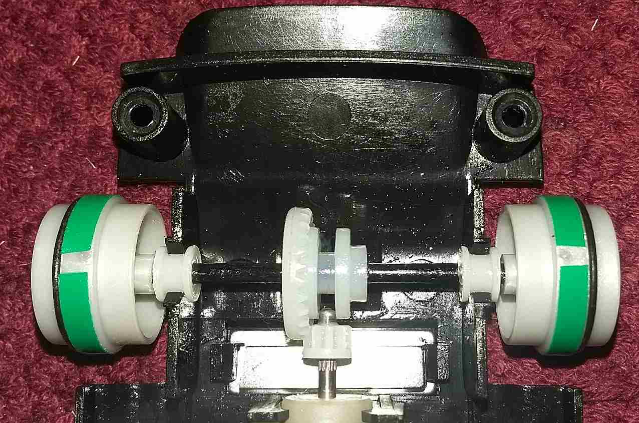
This one may be the last post before Photobucket possibly ruins much of my blogs. Again the GT40 had to come from two laps behind the Chris Mosler to improve the Hotslots laps record to 195.070, this past Saturday 22 July 2017. A small but significant mod to the Professor controller seemed to give the extra finesse, along with a pre race controller service by Lance. Still a fragile open option for most though, the GT40 finished the race with no front axle supports and front wheels......


Just had to record it for posterity but have to claim this Hotslots one for my controller of choice for the Pmb track, currently being the knife through butter double transistor commercial track Professor, which has also proved just the ticket for the South African non magnet Slot.it series, as well.

More by accident than design the same yellow Slot.it GT40 with Scaleauto red 35K at May 2017 now holds the outright open laps record for both the Ecurie Durban and Hotslots Pietermaritzburg tracks, against the field of Moslers et al.


06 April 2017

Formula Libre Pro prep for the metal heads

The Scalextric Lotus Evora super resistant and Ford GT40 are the competitive cars for the Ecurie Libre Pro (with original motor) class at present.

Gavin asked for a shopping list and Paul is commencing preparation of a new Lotus Evora super resistant so this takes the form of a list of recommended bits plus some pictures guide, rather than the blow by blow assembly guide for stock.

Parts sourced locally in Kzn (generally):
Parts sourced overseas:

*         The Slot.it LMP braid is quickly and easily trapped against the guide silver braid shoe and one then threads the lead wire through the hole and (very) quickly solders the wire to the braid (see photos).
          The Mr Slotcar braid is significantly longer lasting but fiddly to tin the end for soldering in view of the capillary action.
**      The only reason for a spacer is so the spur gear does not load against the lip of the pinion during right hand turns, which will load and ruin a motor.
***      The Slot.it 36t 19mm is ample (until worn) but the yellow MB spur is silky smooth and looks zooty.
****    Ash and Dave experimented with a range of different diameter rims (17.3/17.5/18.0/18.3) but the 17.8mm rib diameter rim gives the sweet spot on handling and co-incidentally is the same size as the original plastic rim.
*****   Not a must but nice for body float and the body rear - the coarse Ninco long star screws are great whereas the more common flat head after-market body screws are a pain.

Remember that the Ecurie Formula Libre Pro rules require the magnet relocated to forward of the motor and one should then stack magnet pieces on to achieve the 150 grams target downforce on the Rix scale (minimum 145 grams recommended).

Similar components but different wheel sizes will apply to the Scalex Ford GT40, talk to Ash, Andrey and Lance for sizes. Changing the pinion 11t to 12t will make also make it suitable for Hotslots Pietermaritzburg sports & touring use but remember to change back to 11t for Ecurie! ;-)

Front wheel diameter 16.9 mm (changed)

Note lead wire / braid plus magnet location

LMP braid quick but short term solution

Not cheap but neat rear 17.8 mm rims

36t 19mm spur gear alternative


01 December 2016

Costa concept stock inline car race preparation 2016

Buy the excellent Scalextric GT Lightning and a pack Ecurie stock class rule 8.1 specified Slot.it S2 tyres, along with the option useful investments for the future in the form of cheap 3mm wide trim stripe tape, needle point oiler with thin oil and lighter fluid for cleaning (original can is ok but needle point bottle useful). 
Dave carries a large stock off free pair skinny magnet, 2.5mm thick front O ring, 1.0mm thick rear O ring and one pair "just in case" rear axle plastic spacers as per Ecurie rule 3.3 - just ask and you will receive these. There are other Ecurie experienced who will have similar. My own current source:
Strong-Rare-Earth-Bar-Neodymium-Magnets-N50-25x5x1-5mm
O ring 2.5mm thick by 17mm or 18mm OD
With guide plate in place, flip the top pair braids (brushes) forward as per left in pic. Now only carefully remove the guide plate by sliding forward then lifting rear. Rotate the guide plate 180 degrees and refit per the right in pic. Use will decide if you should trim the rear longer braids but most do and some also replace with other brand braids. This now redundant as Ecurie has amalgamated the GT Lightning Pro and Stock classes and one may now dispense with the clip in guide plate and fit the braids directly to the guide as well, whist Hotslots even allows a switch to a Slot.it guide. The O-ring fronts can also be switched to Slot.it front tyres. Tony at Durban and Oliver at Hotslots are still showing the stock form running gear and wheels to be competitive, though. Now ease the 2.5mm O rings on to the outer front wheels, so the O ring is not "twirled" in the process. I prefer not to glue, if you really must then nail varnish or ask uncle Lance to MEK secure - DO NOT superglue.
The Scalextric wheel centre rib is wrong for Slot.it and other non Scalextric tyres and must be built up with a single layer of trim tape and widened with a single 1mm O-ring on the outside (no glue). Start and finish the trim tape so the rib "pimple" is in the gap, obviating any need to shave the pimple. 
Ease the Slot.it tyre on, sidewall writing inwards (so the ruffle edge also inwards) and "knead" the tyres till well seated and a totallly flat finish with no sign of rib (the sunken cheek finish is what kills the stock motors). Never sand S2, makes the tyre too sticky for stock motors.
The only place I use glue on the whole car, if needed to stop the motor rocking (some motors are tight enough). If you really must remove the motor for any reason, lift at this front point or you will break the rear motor mount. 
The skinny magnets are boon as one can leave the original magnet in place and stack add the skinny magnet without popping out the motor or axle. I break (do not Dremel as heat kills the magnet) the last 20% so that the 80% will clear the plastic clips and sit flat on top of the original magnet. I then stacked the little 20% piece on top (per pic below) and the car came out just shy of the spec 180 gram downforce per Ecurie limit. Use bits of the spare magnet to trim to same, it is worth the time and effort. The finished stack should be pushed forward to the motor mount and will be well clear of the gears. 
Never run a stock motor "wet" with any kind of muti, it burns the commutator black. Dribble in some lighter fluid through the the top little square holes till the bottom of the car is damp then stop and wipe excess. The hi-tech RC approach is to use a slave motor to turn the car motor to seat the motor brushes, the lower tech Mike Wilkie approach of spinning the rear wheels by hand gives plenty gearing to do the job - sitting in front of the tv for ten to fifteen minutes is ample manual run turn time. Once dry then oil all the moving parts of the motor, axles and gears with your new pin oiler or similar.
Ecurie is strict on no butchering of plastic cars so the simple solution is toss the fragile spoiler up front. If you really must fit it then this is the one time you will be forgiven for butchering the locating pins shorter and then bumper taping the spoiler directly on to the car body. Carefully screw the body on to the chassis with the original screws so that the body is loose enough to give about 1mm gap front and rear, there should also be a tiny amount of sideways body float at the rear.
You are ready to run, most cars are fine but some (not all) show excessive rear end axle float, which manifests in a motor killing "Grrrrrk" through the long bends. You should immediately stop as you are hurting the motor and it is time for those "just in case" plastic washers per Ecurie rule 3.3, Dave gave you up front.
This gets tedious and fingerprint removing but one needs to sand the the washers to half the thickness (no don't just put one in, it must be balanced or the motor will run tight). Note the slit (with scissors or knife) so that one can twist and fit over the axle after completion.
This is for example only, just to show where the thin spacers go. Never pop the axle out more than once or twice or you will eventually be obliged to glue the bushes in - you are warned. If the axle still spins freely and the "Grrrrrk" is gone through the long turns, you are now ready to race :-)

Regular maintenance is a must. A day or two before each race night (or minium couple of hours), repeat the lighter fluid dribble through the top of tmotor, clean the mess and manually rotate the wheels for a minute or two only. Then oil sparingly and wait to race. Running the motor "wet" is an anathema, it will bring a short term gain for the first few laps but kill the motor in the not so long run. Also avoid thrash practicing with your new race car for long periods on race evening, just a half dozen laps maximum to settle. The advance motor preparation will give you consistent good performance throughout the evening. 

10 August 2016

New Hotslots Pmb track race video

Macho Mart's Leon achieved something special by managing to follow this A main dice between Lance Cranmer (orange car on black lane), Dave Greer (yellow car on Red lane) and Hadley Woodroffe (black car on yellow lane). 

The lap and a bit down Dave's yellow car catches up to Lance and Hadley on the outer lanes but both immediately lift their game so that Dave cannot pass to try catch up the lap deficit - that only being achieved on Dave's next lane (white) but thereafter both Lance and Hadley pulled away to give Lance 1st, Hadley 2nd, Dave 3rd, Oliver Wills 4th and Dave Gush 5th.


The mob in the pits at briefing and the hand over by Oliver of the obligatory beer to Chairman Arthur, along with the special plaque to be mounted on the track commemorate Arthur's drive and dedication to making the new wood track a reality.


Then it was on to race day action for the 25 participants from the Hotslots Pietermartizburg and Ecurie Durban clubs.


The very first race heat on the new track for driver, Ross, one of the Jacoby twins, Byron and Rodney.


Marshalls ready for race action.


Drivers Gavin, Dave Gush, Freddie, Ashwin, Chris and Tony in one of the heats.


Leon, Kevern and Keith busy in the pits.


Finals results for the absorbing afternoon's racing.

07 March 2016

Britain's best kept clubbie slot car secret? ;-)

I have enjoyed experimenting with transistor slot car controllers ever since assembling a Difalco Junior kit I obtained through Gustav Heymann at the turn of the century. That controller sparked a series of scratch builds, although I have to concede that that ultimate value was still enjoyed from the over the counter Professor, Difalco and Truspeed buys I eventually settled on for magnet plastic slot car racing.

Transistor controllers remain relatively easy for the owner to maintain, often just a transistor replacement being all that is required. 

One and half decades later and midst a softening Rand for South African slot car racers, it was rare treat to again trip over another inexpensive transistor controller byo kit for a donor Parma Turbo chassis (with thanks to RC friend Stan Haussman), available at modest price through the link below, along with detailed graphics and instructions:


Even for total novice slot racers, the kit is simplicity itself to wire up. I was fortunate enough to entice returning slot car racer and multiple South African champion Johan Louter in to tackling it as an initiation to transistor controllers. Transistor and PWM controllers are new concepts for Johan, who still retained his trusty rectifier diode controller from when he retired from racing just after the turn of the century.

Pardon the fuzzy cell pics of the final product, which is ultra compact, clear of controller case top clutter and very light, given the Turbo chassis combo:


I did much googling to try find some outside commentary on this excellent kit, which Truspeed's Steve Hill had evolved as an inexpensive option for Britain's clubbies to put together. An unusual element not seen on other transistor controllers is the use of transistor braking as opposed to the normal wire wound or diode pot, along with the brake and hold feature mentioned in the Truspeed blurb. The total lack of Google find reviews or commentary thus convinced me to publish this on the blog and get the word out. I can only assume the clubbie's were keeping this gem secret to themselves. ;-)

The main test vehicle for the controller was my open magnet racer Slot.it GT40 with trusty Scaleauto 35K red motor. This combo has been a useful Ecurie open and handicap option for me but pretty much red lined at 4.5 second laps on the Ecurie track. The outright lap record for open magnet had previously been set at 4.3 seconds with Lance Cranmer driving my Proslot Toyota GT1, also powered by the Scaleauto red 35k motor.

After being suitably impressed at my own efforts with the Truspeed and the GT40, it was time to entice Lance back for another crack at a useful lap time. He too was impressed with the knife through hot butter feel of the controller and, as per the pic below, the rest is history with a new outright lap record and constant 4.2 second laps. 


The same car / controller combo also broke the laps final record at the recent open magnet event. :-)

Truspeed have now gone one better than their Transistor kit and will be producing a complete transistor controller at a very good value price:

Truspeed BP2 transistor controller

Update:

Friday 22 April Open Handicap - extract

"Secondly, the Truspeed controller continued to weave its magic with the aging Slot.it GT40 and not even its owner in his wildest fantasies would have contemplated again breaking the laps record, this time by a whopping three laps, to take it to 156 laps, like Ash did with 1/24 production record earlier in the month."

Latest and final update:

Friday 26 August Open handicap - extract

"From a personal perspective, the steady improvement had looked red lined at 157 laps, although last month’s 157.96 was knocking at the 158 door. Qualifying was very, very nervy and the race only slightly less so but it is with thanks to Truspeed controllers and track-clean Lance that the same GT40 frog-leaped the plastic race record by almost four laps to the new ultimate record of 161.69 laps. Whilst I am confident that Ash, Lance and co. will soon attain same and beyond, it is time to tick the 160 lap holy grail box and retire the GT40 and slightly crazed speed to shelf queen status."

The ultimate best lap time with the BP Controller:


Sub 4.2 second lap time with the brand new production version Truspeed BP2 controller, which features adjustable spring tension (the plug mounted pot not required):


14 March 2014

Sort those traction magnets!

It is pretty much common knowledge that not all magnets are of equivalent strength and some even vary wildly in strength between the north and south poles! There is an obvious upside to sorting out the good from the dud magnets and also marking the side with stronger magnet attraction so that faces down to the track.

The magnet strength is termed "gauss" and there is a very cheap and simple way to make your own tester, using a hall effect device and voltage regulator, totaling twenty bucks from Mantech and other electronics shops. Most have their own multi-meter or if not, these are cheaply bought from places even like Osmans or your nearest electronics shop. The black mini multi-meter in the pic cost me twenty-five bucks so not a huge investment.

The hall device measures 0 to 2.5 volts for the north pole and 2.5 to 5 volts for the south pole. Either convert the south pole reading back to 0 to 2.5 volts on your calculator so the measurement is same and just use the voltage or convert both to gauss for a common reading, as well.

There are some links to the "techie" document at the end or simply go with the extract text I found the most useful and put below. A spreadsheet conversion excel file is downloadable to save you own number crunching or simply print off the mini summary, which seems to cover the range of 25 mm traction magnets we use.

Below is the two components built on to some vero (perf) board, showing a voltage reading of 3.39 volts with a tyre as spacer. reference to the table or calculator gives the gauss number. I cut out the completed circuit portion of the board and glued the whole caboodle under an old slot car case base to give somewhere between 4 mm and 6 mm gap between the magnet and hall reader - any jig will do. The guy in the article was only using a ferite magnet so was able to rest directly on the hall reader, our traction magnets are far too strong for that.


The invoice is for the un-calibrated hall effect device and five volt regulator that was purchased, reference the article for more detail. Also two small crocodile clips to clip on the multi meter probes. Below is the extract picture from the article that I followed in conjunction with the text extract below that. Note the writing faces up on both gizmos and you then can follow the logic:


"Now, how do you make it?
Connect the + (red) of the battery clip to the input of the 7805 (pin 1).
Connect the - (black) of the battery clip to the common of the 7805 (pin 2).
Connect the +5V input of the Hall device (pin 1) to the output of the 7805 (pin 3).
Connect the common of the Hall device (pin 2) to the common of the 7805 (pin 2).
Set the voltmeter to read 20Vdc max.
Attach the + of the voltmeter to the output of the Hall device (pin 3).
Attach the - of the voltmeter to the common of the 7805 (pin 2) or the common of the Hall device (pin 2).

You are now ready to snap a battery onto the battery clip.
The red lead from the 9V battery goes to pin 1 of the 7805. The black lead from the battery goes to pin 2 of the 7805. The output of the 7805 (pin 3) is connected by a green wire to pin 1 of the Hall device. Pin 2 of the 7805 is connected by a black wire to pin 2 of the Hall device. Please note that the marking on the Hall device (giving its part number) is facing the camera. The voltmeter common (black) is connected to pin 2 of the Hall device. The voltmeter input (red) is connected to pin 3 of the Hall device. (I got the voltmeter from a Home Depot store near here for about $20.) That's all there is! Great, or what?!
The voltage at pin 3 of the voltage regulator. Ideally it is 5.00 volts, but we measured 5.02, which is close enough.
The output of the Hall device when no magnet is nearby. Ideally it is 2.50 volts, but we measured 2.59. This would be our V0 as noted above. The Hall device I have here is an Allegro UGN3503U, with a sensitivity of about 1.3 mV/G."

One assembled and good to go, either download the full spreadsheet here:

Or click and print off this graphic that has the range most magnets tested operated in:

Having completed the project, I found this circuit I must have downloaded previously (apologies for not crediting its owner), which is a bit more larney with switch and led light and maybe easier to follow:


A small investment in time and money and gold dust for magnet racing!


10 March 2014

BYO multi board thirty band controller for 1/32 racing


This one is for those tight on local Rands and willing to do a relatively simple bit of handiwork to give themselves the versatility similar to the 1/32 Difalco 30 band controller, especially if contemplating something like non magnet plastic racing in addition to magnet racing, where alternative resistance boards are a must.

One way is to source a Parma turbo controller and bolt on:
1.   1/24 difalco conversion module economy rheostat slot dd253-hd30
2.   for that "feel" Difalco ball bearing upgrade kit w/trigger pin
3.   If you really want to go the whole hog (not necessary) - Difalco diy genesis frame kit w/trig pin

Using the conversion module instructions and this useful little pictorial which shows how to modify the Parma Turbo frame and fit the board - the board is different but the assembly and hook up precisely the same:

Or one can go the cheapie approach I used for Craig's controller, using the Euro style pnp transistor and simply bolting (with bolt insulation) the pnp transistor to the Parma Turbo frame and following the simple hook up. I recommend using the 1/24 upgrade board with 148 ohm for magnet racing and purchasing a spare 290 ohm board only if you intend non magnet racing.

For this approach source a Parma Turbo controller and bolt on:
3.   R12     From Mantech or many electronic shops, the Tip36c Transistor
4.   £7        Brake pot Wirewound 4W Power Potentiometer 25-Ohms (50 ohms ok as well)
5.   £7        Sens pot Wirewound 4W Power Potentiometer 50 Ohms (25 ohms ok as well)

Just follow the hook up guide in this picture using colored wire, cut completely though the board rail shown between H and C so there is no continuity and you good to go. No cutting of the existing wiring other than splicing in to the existing white and black cable and chopping and extending the red cables to hook to the 25 ohm brake pot, which is bolted on along with the 50 ohm sensitivity pot, which is soldered on where shown. That's it you done.


This the assembly sequence for the Craig pnp controller:

Bolt on upgrade board and transistor and cut frame heat sink

Note screw insulator for transistor and home made "L" brackets to hold board to frame

See it fits and chop case to suit

Chopped Case

Wiring and wiper arm added

Hook up to back of upgrade board.
That is pretty much it. If you prefer to go with the original US npn transistor approach then you don't have to cut through the track between H and C but you do have to insulate the wiper arm from the wiper base using tape on similar, as per the detail hook picture below:


On my version I used a Difalco replacement power transistor 1/32 for $7 or you can local and cheap with the Tip35c npn transistor for about R14.

Once complete, if you wish one can add a 30 amp or more automotive relay. One has to disconnect the white cable from the full power stop and connect in a new "skinny wire" from the relay to the full power stop. The rest is hooked up as per Jim Difalco: The brake wire is on #86, the skinny control wire that turns on relay is terminal #85. Then the two main black and white controller wires go to terminals #30 and #87 (does not matter which goes where).

Changing the Wiper arm button to floating is also recommended, guide as per Jim Difalco:

A floating button is pretty simple. About 1/4" below the wiper button hole bend the arm down, towards the circuit board, at about a 30 degree angle. Next at the centre of the wiper button hole bend the arm up at a 30 degree angle. Make sure you make both bends parallel to the top of the trigger. This setup with all the wiper pressure on the centre of the button lets the button pivot top to bottom. This is needed so when you pull the trigger the top or bottom button edges do not lose contact because of the play in trigger bearings.

Next file the face of the wiper button flat. File the face of the stud and tin it with solder. Now install the trigger in controller. If you have an electronic type controller solder the skinny wire to the wiper button stud. If it is a resistor type controller solder a short 1" piece of leadwire from the stud to the wiper contact that is over the wiper arm to ensure connection. Leave a little slack here, do not run the wire straight from button to trigger contact. The button needs slack to pivot. 

Tips: if you are trying this on a resistor controller the wiper button edges should be rounded off. If you are trying this on a Parma resistor that resistor should be sanded flat or you will be causing the button to catch the edge of any high band.

Adjust the wiper arm tension by gently pulling it away from the wiper board. Check that the wiper button does not lose contact as you pull the trigger across the contacts. Also check that the button contacts the first band at the front edge of the button. If it does not, you can twist the front edge of the wiper arm down until this happens.