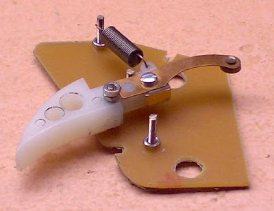
Defeated by the funnies of scanning, it steadfastly refuses scanning as a graphic (maybe the shine?). The scale is haywire but have something half workable after photostating. The print should measure 39mm mid point to mid point of the large 8mm holes.
The notes:
1.Masking tape the metal part of the PC board.
2.Plan your cut so the top right hand corner is used in each case. Minimises the number of cuts and is cost efficient as four boards come out one 150mm by 150mm board.
3.By all means add a bit more meat to the top but otherwise cut exactly on the line or even inside, it is such an exact fit in the case. The bottom left hand “tongue” can be lopped off if wanted, I left that there so the template outline can be used for other trigger combinations.
4.The original board locks in to the case, if there is wobble then one screw in the region of the brake stop (or the brake stop bolt itself) can fix the board to the left hand case – no others needed.
5.Eight mm for the main holes, 2.5mm for all the trigger related bolts and 2mm for the top two holes holding the wiper pad.
6.Use two RC servo mounting eyelets as the ideal spacer to bring the wiper pad up to the height of the wiper.
7.Score the two lines through the metal to break the contact surface in to brake (red) / throttle (black) / full (white).
8.Remove some of the board metal surface around the left hand wiper pad screw, under no circumstances should the “brake band” on the wiper pad be live, only the brake stop, as there is no dead band facility on the wiper pad.
9.A small part of the case top will have to been removed to all the resistors to peek out the top..
Assemble, fit pots to the case and connect up and ready to race.
Reference item 7. If one wanted to use a stock economy mechanism without stops, then the first band after brake is left dead and the brakes connected to the brake band. One then only has an 11 band controller for the throttle portion.


